| STEP 1 |
(Enlarge) |
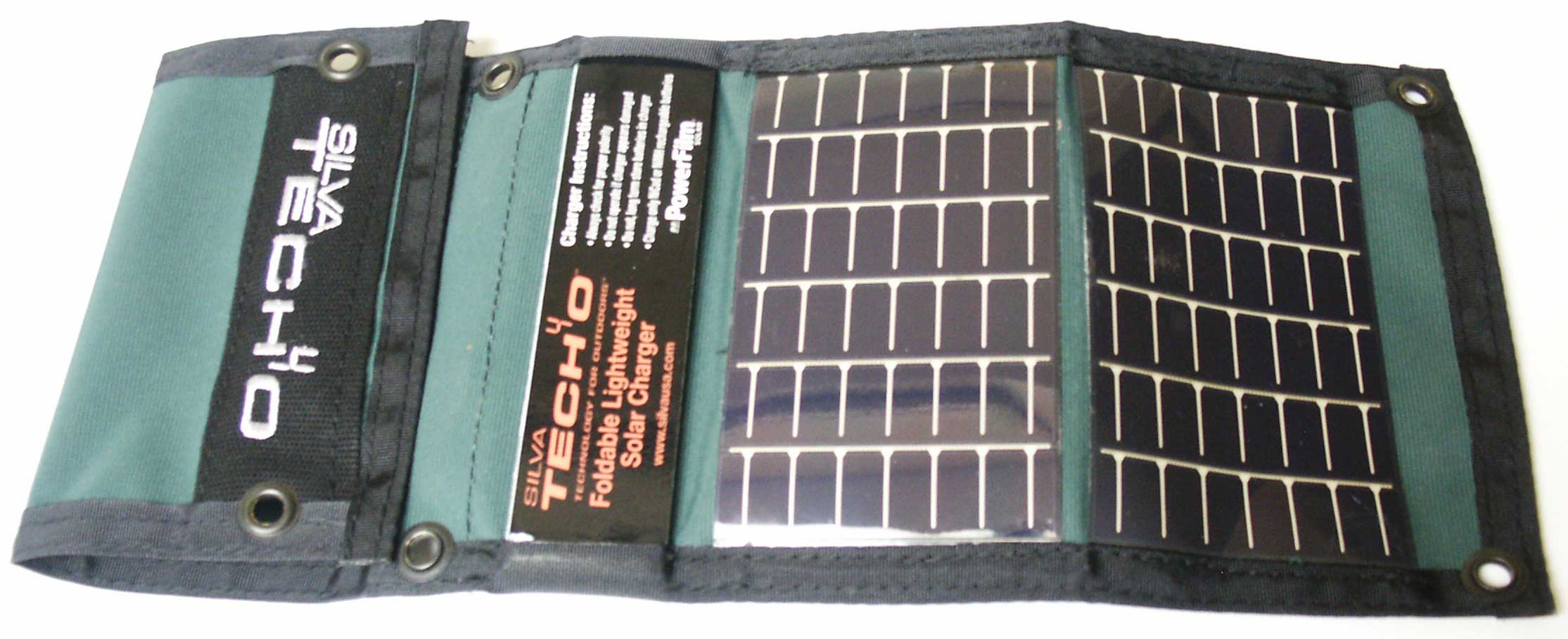
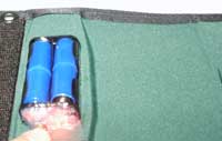
- Place the solar charger as shown.
|
| STEP 2 |
(Enlarge) |
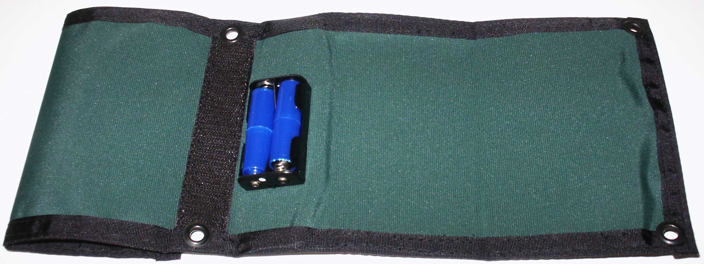
- Flip over the solar charger. The end facing you should be the end that you will be soldering the modifications to. To verify this, look for two small holes in the battery holder nearest you. The side of the battery holder you will modify is the side that the solar panels are connected to.
|
| STEP 3 |

(Enlarge) |
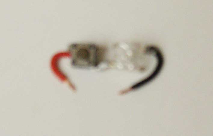
- Perform a continuity test on the tact switch (to make sure it works) and as well the red led.
- Solder a 3/4 inch long, red colored, 22 gauge wire end to one of the leads of one of the tact switch.
- Solder the positive lead of the red led to the lead of the tact switch that is diagonally positioned from the lead that you soldered the red wire to.
- Solder a 3/4 inch long, black colored, 22 gauge wire end to the negative lead of the red led. You may want to clip the other two leads of the red led since they are not used and could get in the way later.
|
| STEP 4 |
(Enlarge) |
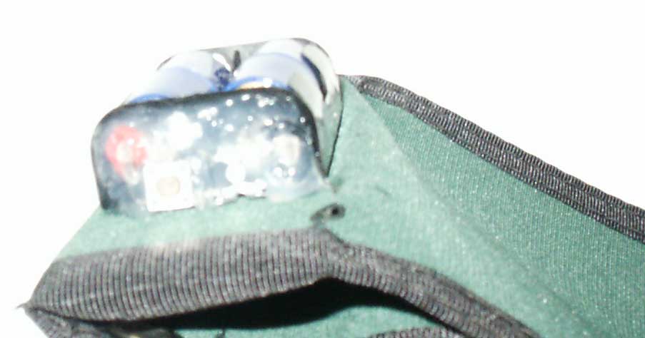
- Solder the positive lead to the positive post of the battery holder (outside).
- Solder the negative lead to the negative post of the battery holder (outside).
- Carefully adjust the position of the wires, tact switch and red led so the components are flush within the surface area of the side of the battery holder. Make sure there is a small gap between the tact switch and red led and the side of the battery holder (3/16 inch is sufficient).
- Place the solar panels towards the sun or near a light so that you can press on the tact switch and have the red led illuminate (if it does not illuminate either (1) the solar charger is defective, (2) the light source is not strong enough, or, (3) there is a faulty soldered connection that you'll need to fix.
|
| STEP 5 |

(Enlarge) |
- Apply the silicone sealant between the components and the side of the battery holder. You may also want to apply the silicone sealant around the sides of the tact switch and the red led so that those components will be more stationary (and less likely to separate or break off from the silicone sealant if they are bumped).
|
| STEP 6 |
(Enlarge) |
- After the silicone sealant has dried, it is time to perform another test of our charge indicator modification.
- Insert either charged "AA" or "AAA" batteries into the battery holder and press on the tact switch. The red led should brightly illuminate.
- Congratulations! Now you have a compact way to tell when the batteries are charged - when the red led is dull or not illuminating at all you know more charging is needed and when it is bright the batteries are ready to be used.
|
| STEP 7 |
FINAL NOTES |
- Why is this modification so simple? The biggest reason this modification is so cheap (approximately $7.00), is that the red led used (which produces red light) operates at a voltage of 2.6 - 3.3VDC. This means that the red led will only create bright illumination at 2.6VDC. Most single batteries are rated at 1.25VDC; a pair of them would create 2.5VDC...that correlates to the voltage required by the red led to operate at it's typical rating. The maximum voltage of 3.3VDC of the red led provides a buffer in the event the batteries contain higher voltage so that it does not burn out.
- When you perform a test of how much charge is contained in the batteries, be sure to cover up the solar panels; otherwise the power created by the solar panels will be picked up by the red led instead of the batteries.
- In order to prolong the life of the solar panels, be sure to remove the batteries when the solar panels are not charging them (such as when the sun goes down). If you do not do this, you risk having the power from the batteries go into the solar panels and damage them (this is the case with any solar panel that is not protected from reverse voltage). Damaged solar panels will produce less power and it will take longer for batteries to charge.
|