Main Page
 The gatekeeper of reality is
 quantified imagination.

Stay notified when site changes by adding your email address:

Your Email:

Bookmark and Share
Email Notification
Project Battery Charger
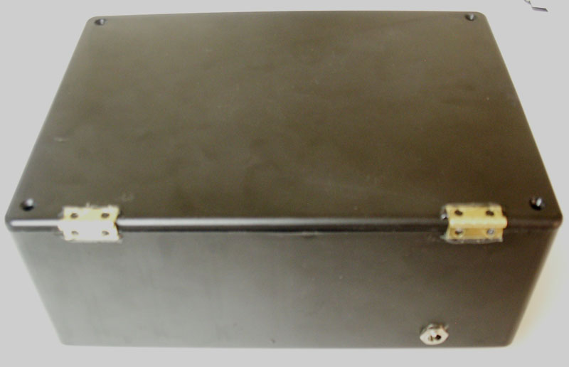
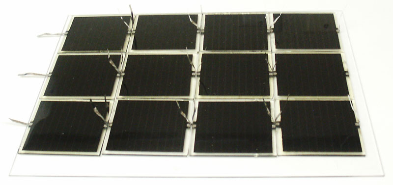
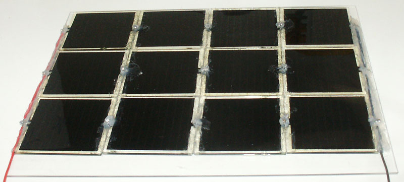
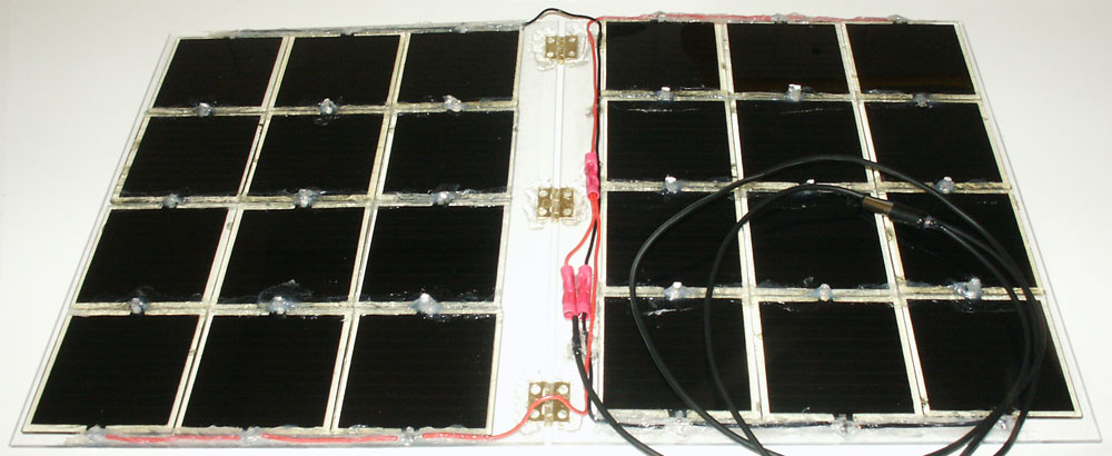
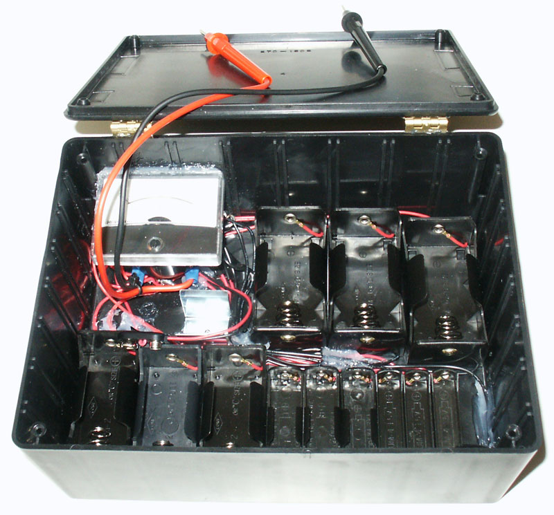
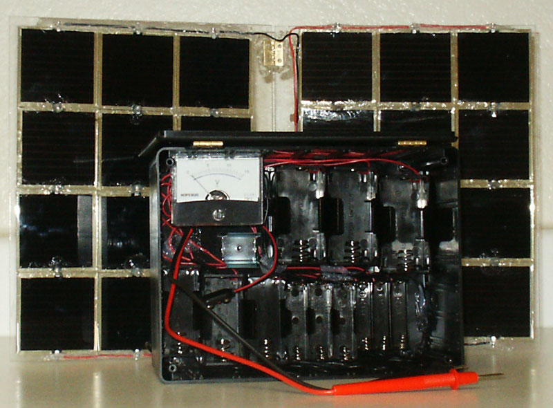
    Purpose
The purpose of this documentation is to demonstrate how I put together a solar battery charger for AAA, AA, C, D, and 9V. This particular solar battery charger takes power from a folding solar panel rated at 12VDC/240mA to a series of battery holders (three each of AAA, AA, C, D and one nine volt) that are all connected in parallel. A analog voltmeter 0-15VDC is also included so that you can measure the voltage of different batteries. Since the folding solar panel outputs 12VDC it has the capacity to overcharge batteries. As an example, I put in three AAA 1.2VDC NiMh batteries (already at full charge of 1.2VDC and after 3 hours in sunlight the three batteries were up to 1.35VDC each).


(Enlarge)
  1. The first place to start is to glue hinges to the 6 x 8 plastic box (will hold the battery holders and meter).
  2. Add the power jack to the hole and solder the blocking diode (positive lead) to the negative lead of the power plug.

(Enlarge)
  1. Glue the silicon cells, face up, onto the acrylic sheet (to create a 3 x 4 cell matrix). Be sure to orient the cells so that each row is connected in series.
  2. Create a second panel in the same manner (you could create more than just two if you want batteries to charge faster).

(Enlarge)
  1. After the glue has dried, solder the positive leads together as well as the negative leads. Encapsulate the leads in the glue so that the ends and wire don't move (the tin connections on the solar cells are fragile).

(Enlarge)
  1. Glue hinge ends to each panel and attach wire (containing the male plug) to the foldable solar panel).

(Enlarge)
  1. Connect all the positive leads of the battery holders together and connect that to the positive end of the power jack that you've attached to the box.
  2. Connect all of the negative leads of the battery holders together and connect that to the negative lead of the diode (the positive lead of the diode is attached to the negative lead of the power jack connected to the box). This helps ensure power only goes from the solar panel to the batteries and not visa versa.
  3. Glue the battery holders to the box.
  4. Connect the test leads to the analog voltmeter. Glue the analog voltmeter to the box.

(Enlarge)
  1. When completed, the project should resemble what is pictured.


Project Materials
[1] Project Enclosure (8x6x3")
[1] 2.5OZ Liquid Nails Clear Adhesive
[1] Loctite® Stik ‘n Seal® ULTRA
[1] 0 - 15 volt analog voltmeter
[2] 10" x 8" x .080" clear acrylic sheet - Optix
[1] 8A 45V Schottky Barrier Diode
[1] Heavy-Duty 9V Snap Connectors
[1] 9-Volt Battery Holder
[3] Single AAA battery holder
[3] Single AA battery holder
[3] Single C battery holder
[3] Single D battery holder
[1] Size M Panel-mount Coaxial Power Jack w/Switch
[1] Size M Coaxial DC Power Plug
[24] Solar Cell, 60MM x 60MM x 2MM CAT# SPL-61


About Joe