| STEP 1 |
(Enlarge) |
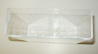
- Create slots on one side of the 11 x 9 x 3 inch box; the female ends of the Deans 2-Pin Ultra Plugs to be seated and glued in.
- Place 1/4 inch acrylic cubes around the perimeter of the acrylic sheet so that when the acrylic sheet is placed over the box, one edge of each cube is in close proximity to the inner wall of the clear box.
|
| STEP 2 |

(Enlarge) |
- Glue the Mini Fuse Style fuse blocks to the opposite side of the box.
|
| STEP 3 |
(Enlarge) |
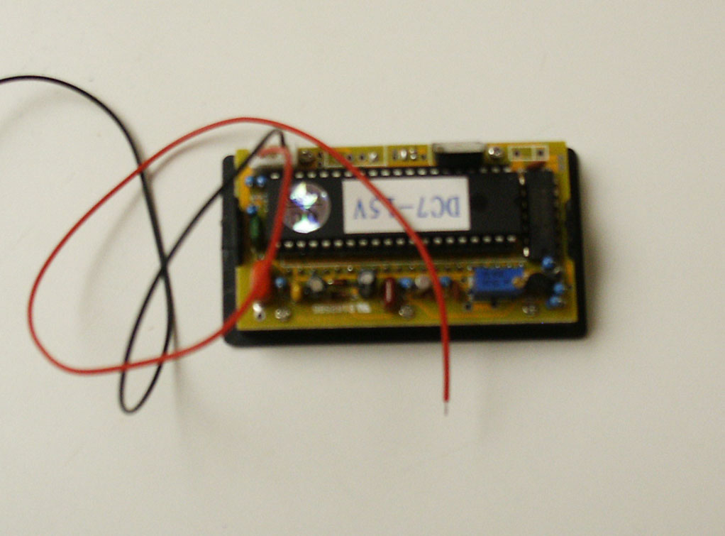
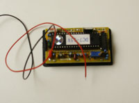
- Cut off the two plastic snap-clips from the digital voltmeter.
|
| STEP 4 |
(Enlarge) |
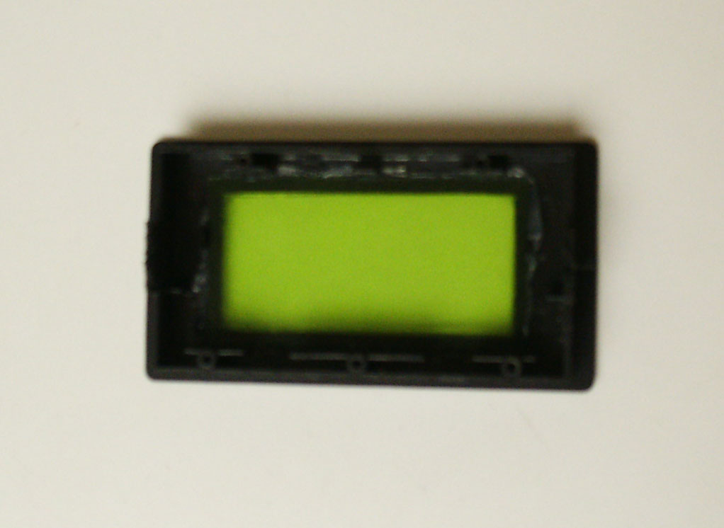
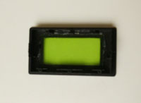
- Remove the faceplate from the digital voltmeter.
- Apply silicon sealant around the perimeter of the colored, transparent plastic plate and allow it to dry. This will prevent the epoxy from leaking around it.
- Reattach the faceplate to the digital voltmeter.
|
| STEP 5 |

(Enlarge) |
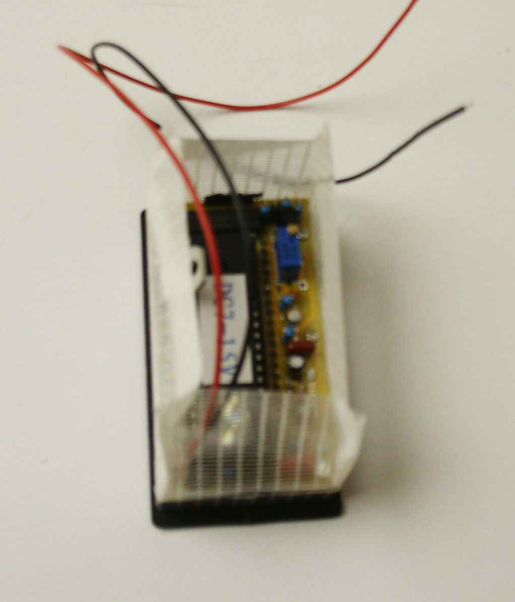
- Take a 10 inch strip of packaging tape and stick it to the perimeter of the digital voltmeter. Ensure that it is applied properly so that the epoxy does not leak out.
- NOTE: The reason why epoxy is used is to create a seal over the meter's electronic components to help reduce the likelihood of the components degrading prematurally due to moisture, dirt, battery acid fumes (if not using AGM), and so forth.
|
| STEP 6 |
(Enlarge) |
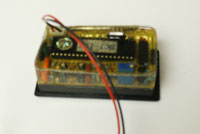
- Mix a portion of the 1:1 epoxy so that you have enough to fill approximately 60% of the volume created by the tape and then pour into that area.
- As the epoxy fills in areas of the digital voltmeter you may need to add more to ensure that the electrical components of the digital voltmeter remain covered.
|
| STEP 7 |
(Enlarge) |
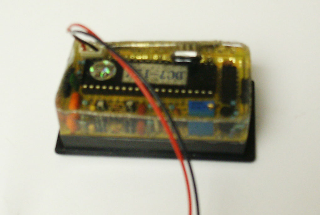
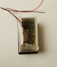
- After the epoxy has dried (approximately 24 hours), remove the tape. You will notice that the epoxy has dried into the form created by the tape.
|
| STEP 8 |

(Enlarge) |
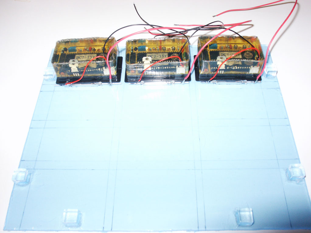
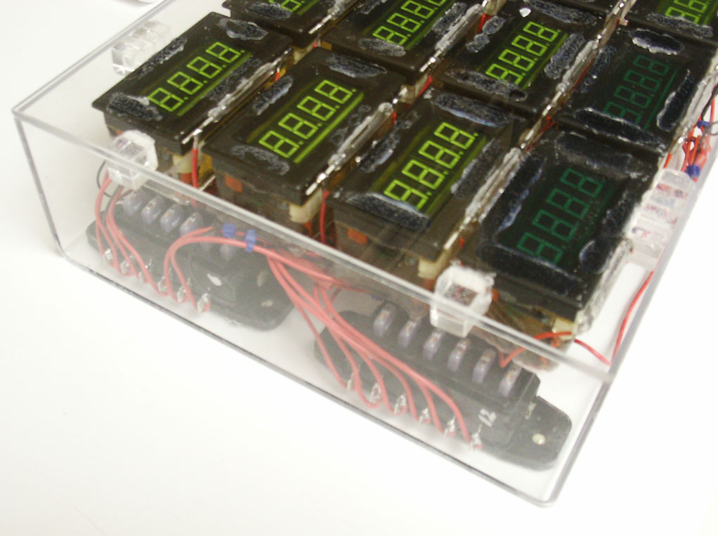
- After you've completed with all digital voltmeters, glue each one onto the acrylic sheet.
- Be sure to also glue a reed switch below each digital voltmeter and solder wiring as shown.
|
| STEP 9 |
(Enlarge) |
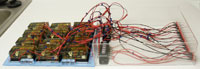
- Solder the positive wire (red) of the reed switch to the blade of the Mini Style fuse block.
- Solder a positive wire (red) on the corresponding opposite side of the Mini Style fuse block and solder the other end to the to the positive blade of the Dean 2-Pin Ultra Plug (female).
- Solder the negative wire from the digital voltmeter (black) to the negative blade of the Dean 2-Pin Ultra Plug (female).
|
| STEP 10 |
(Enlarge) |
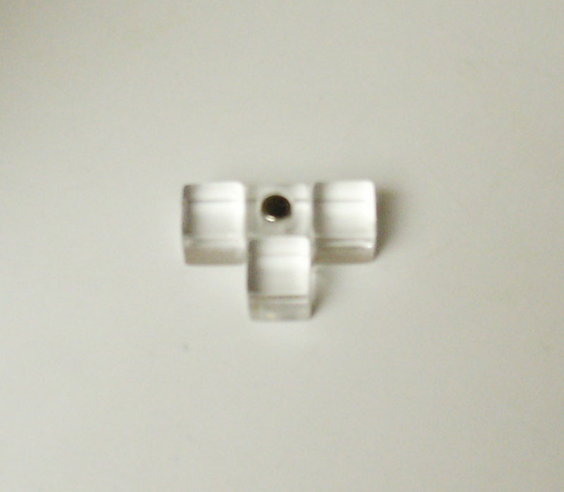
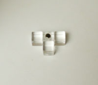
- Since reed switches are being used in place of traditional switches, we need a way to close the contacts of the reed switch. This is accomplished by using a small magnet.
- Glue four 1/4 inch acrylic cubes together as shown.
- Drill a hole into the center acrylic cube, place silicon sealant into the hole and slip the small magnet inside so that the exposed end of the magnet is flush with the surface of the acrylic cube.
|
| STEP 11 |

(Enlarge) |
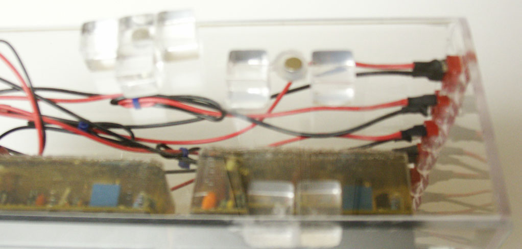
- At the top of the clear box, glue a small magnet to the inside and two 1/4 inch acrylic cubes on the outer surface. This is to provide an area for the reed actuator (previous step) to be placed when not in use.
|
| STEP 12 |

(Enlarge) |
- This photo illustrates the placement of the reed actuator so you can see how the two cubes seat the reed actuator and the small magnet inside of the clear box is attracted to the magnet in the reed actuator so that the reed actuator does not move.
|
| STEP 13 |

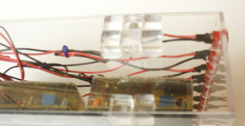
(Enlarge) |
- This photo illustrates the advantage of the clear box in relationship to the fuse blocks and fuses it contains. Each of the fuses illuminates when it is burnt out; by being able to glance into the clear box you can identify which fuse(s) may be burnt out in order to replace them.
|
| STEP 14 |
(Enlarge) |
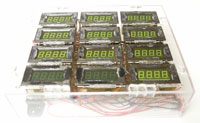
- After looking at the front of our solar battery bank monitor, all of the glue adhering the digital voltmeters to the acrylic sheet is visible and may be distractive.
- In order to fix this visual "blemish", you can paint borders around each digital voltmeter that will cover that up. It will also provide a solid colored background for writing (which will make the writing easier to see).
|
| STEP 15 |
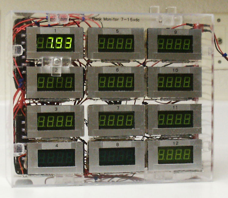
(Enlarge) |
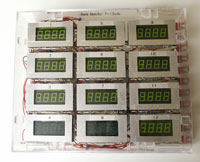
- With the borders applied and allowed to dry, each digital voltmeter is marked sequentially from 1 to 12. You should also mark each Dean 2-Pin Ultra Plug female plug with the same number as the corresponding digital voltmeter.
|
| STEP 16 |
(Enlarge) |
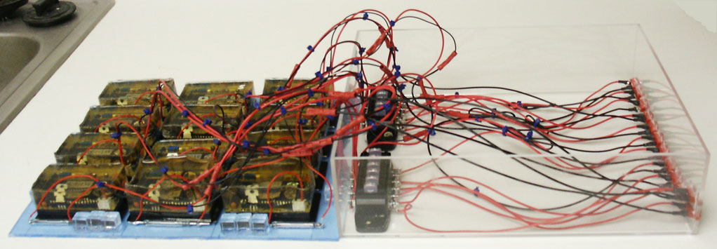
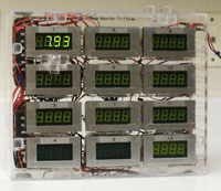
- Congratulations, the solar battery bank monitor is complete!
- In this photo we see that the reed actuator is placed over the reed switch of the first digital voltmeter (closing the circuit) and we see a digital read-out of the voltage of a single battery (in this case, a 9 volt battery for testing).
- The voltmeters, in use, are connected to 12VDC @ 100Ah batteries (weighing approximately 70 pounds each) and have operated fine (as you can imagine, the 70 pound batteries are considerably larger than the 9 volt hand-held battery used for testing).
|