|
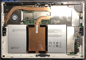
After heating the display on a pad to soften the adhesive around the edges of the tablet, I was able to separate the display as shown. I then removed splotches of adhesive that remained (so that there is a smooth and uniform surface when the display is re-attacheed).
TIP #1: If you look at the picture, do you see anything that is strange with one of the edges? Well, it turns out that if you have a Surface Pro 4 tablet with a wifi antenna, it sits along one of the edges. If you notice here, after separating the display from the frame (the tablet had the original factory build so it had never been opened), I had sliced through the very thin antenna flat wires.
TIP #2: The Surface Pro 4 tablet, oddly, had 2 different display connection end-points depending on whether you had a LG or Samsung variant of the tablet. If the display needs to be replaced, here is some information that I came across that could be useful to know:
Samsung (LTL123YL01) - 25-pin (50-pin total) connector for the 2736 x 1824 LCD touch screen display.
LG (LP123WQ1) - 32-pin (64-pin total) connector for the 2736 x 1824 LCD touch screen display.
I would also throw in that, a display version like LTL123YL01-005 may also require a separate L-shaped digitizer board (which is attached to the corner of the display via adhesive strip) of the same type...I have no idea if a substitute digitizer board for a "LTL123YL01-003" would work for a "LTL123YL01-005".
|
|
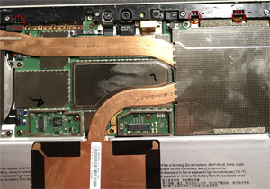
This is a close-up photo of the red-circled wifi antenna connection points I had sliced through, not knowing they were there. The factory adhesive strip sat on top of the wifi antenna strip. Convenient.
|
|
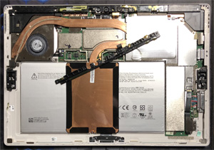
Finding the antenna strip and replacing it was quite simple though, as you can see.
|
|
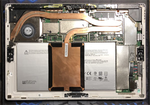
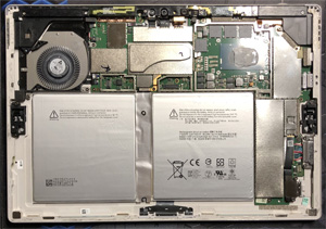
The next thing to pull is the CPU shield, so that you can remove the heat-sink assembly.
|
|
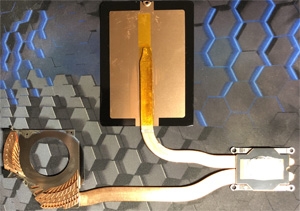
The next thing to pull is the heat-sink assembly.
|
|
Here, the heat-sink assembly has been removed. It should be noted that while the large flat plate of the heat-sink was over the battery, there was no heat-sink paste present on that large flat surface. With the black tape around the edges and a plastic strip covering one of the heat-sink arms, I'd guess the large flat surface is not meant to make actual physical contact with the battery but, rather, radiate heat from the CPU into the battery area to compensate for heat not able to be dissipated by the cooling system's fan (perhaps if the fan stopped working?)
|
|
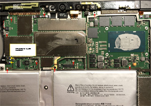
Next, I disconnected the two connectors (see yellow arrows) and removed several screws of the main board (see red arrows). This will allow the edge of the board, nearest the battery, to be lifted so that the battery can be removed. Also, the battery is glued to the frame with two exceptionally large adhestive strips as will be seen later.
TIP #3: The battery connector has a hole in it. This hole actually slips over a small round peg in the frame and keeps the connector from moving around. Because of that, the board needs to be lifted a bit so that a tool can be used to lift the connector over the peg so that the battery can be removed.
TIP #4: The battery connector also has an adhesive strip that attaches it to the frame, so a thin separation tool will be required to get through that adhesive (and lift the connector over the peg).
|
|
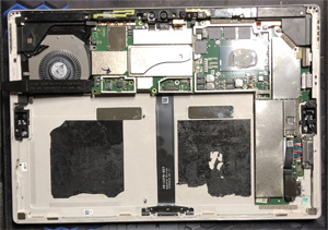
Here, the battery has been removed and you can see just how large the factory adhesive strips are for the battery.
|
|
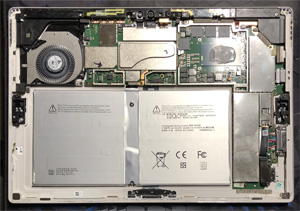
In this step the new battery is attached and seated; a thin strip of adhesive glue like T-7000 was added to keep the battery from shifting; the adhesive is slow-drying but you don't need lots of it. In order to get the battery connector's hole (with the two copper strips facing up toward the main board where the connection contacts are) to "fall" around the frame's peg, I pushed the connector cable down a little bit past the peg while aligning the battery connector as best as I could.
I found it impossible to actually get the battery connector's hole to fall around the peg with the board as elevated as what it had been. Then I pulled the wedge most of the way out (which has been holding up the board) so that pressure was applied to the battery connector. Following that I gently pulled on the battery until I felt a little snap and a clicking sound (indicating to me, at least, that the peg was now in the hole of the battery connector). To verify that the battery connector was where it needed to be, I was not able to pull the battery (and its connector) away from the board.
Following that, the wedge tool was completely removed, the screws were put back in place and the two flat connectors were re-attached.
|
|
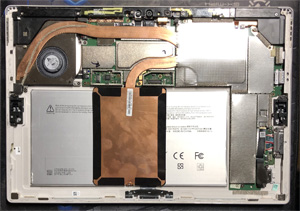
After cleaning the surface of the CPU (and surface of the heat sink) and applying fresh heat-sink paste like XTM-70, re-attached the heat-sink assembly and the shield.
|
|
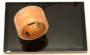
Finally, the screen is reattached and seated. In this particular case, however, I did not use the adhesive strips or adhesive glue to bond the screen to the tablet.
After recalling the issues I originally had with separating the screen from the tablet (like the wifi antenna mentioned earlier) I realized that, given the quality of batteries today (and not wanting to also replace another antenna where the adhesive strip sits on top of)...the battery might have to be replaced again in a few years.
So, instead, I opted to use some high strength transparent tape along the edges of the screen effectively taping the screen to the tablet. Then, in the future, if I need to open the tablet I can simply peel off the tape or use an exacto to cut the tape. OMG, so easy - and a time-saver.
|
