Main Page
 The gatekeeper of reality is
 quantified imagination.

Stay notified when site changes by adding your email address:

Your Email:

Bookmark and Share
Email Notification
Range Raider
Range Raider
Range Raider


Introduction
Click Enlarge
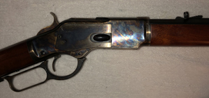
Figure 1: Winchester 45 Colt Model 1873 Uberti
The Winchester 45 Colt Model 1873 Uberti lever action rifle is one which incorporated built-in sights with an adjustable elevation alignment. Given its overall design with a fixed under cartridge magazine, side cartridge feed, top ejection chamber, tapered wood grip and butt stock, the ability to add modern components such as an optical scope or laser to enhance sighting a target has been largely impossible.

The idea I had in looking at the design was how a picatinny rail could be added to the rifle without modifying the rifle itself so that an optical scope could be attached to it as most modern rifle today are designed. While adding a picatinny rail with this particular rifle design is a big challenge at first glance, it is not impossible as this article will describe. This article also includes CAD (Computer Aided Design) files that were used to manufacture a Range Raider bracket system plastic prototype with a 3D printer. This was to determine fit (manufacturing tolerance is likely to vary from rifle to rifle with the potential consequence of the bracket fitting too loose or too tight) before I moved on to machine the equivalent in a sturdier material such as 6061 T6 Aluminum. In that regard, I made a few changes (such as extending the bolt areas) to reduce the number of cut angles being made (to improve end mill tool life as well as lessen alternating axis movement of the machine).

[Download CAD zip file (10 MB)] CAD and Gcode Files of the Range Raider


Anchor Points Across all Axis
Click Enlarge
Figure 2: Anchor / Stability points suitable for a mounting bracket
The challenge to adding a rail to the rifle is determining where, how, and unobtrusively, a bracket could be attached. Realistically, with this particular rifle design there is only one small area that satisfies the stability requirements needed to exploit a rail (from which an optical scope may be attached).

As illustrated by Figure 2, the anchor points are reliant upon the barrel, the point the barrel enters the metal assembly as well as the side and lower surfaces and the angled metallic elevation sight. While the angled metallic elevation sight was a challenge to design for given its backward offset from 90 degree to the horizontal plane of the barrel, that offset provides a unique 3-point anchor; that is, a limiter to forward movement of a bracket as well as movement upward and downward.
Click Enlarge
Figure 3: Picatinny rail position relative to bracket block, ejection chamber and slide, hammer and cartridge feed
The other major consideration for the rail is where it would be positioned (via a bracket) on the rifle. Positioning it over the existing barrel would be far too forward for an optical scope. However, positioning the rail over the metal assembly presents 3 challenges being (1) cartridges are top ejected unlike most modern rifles, (2) a protective ejection chamber slide utilizes a majority of the top surface area of the metal assembly, and, (3) the thumb hammer extends beyond the top surface as seen by Figure 2. The remedy to those challenges is to add arms to the bracket block that will hold a mounting plate behind the ejection chamber for the rail at a height above the top surface to allow both the slide and hammer to operate without mechanical interference as demonstrated with Figure 3.


Constructing the Range Raider Bracket in Metal
Click Enlarge
Figure 4: 3D printed prototype of the Range Raider for test fitting
By far the easiest, though not necessarily the most economical, method of manufacturing the bracket would be to 3D print a G-Code file derived from the STL file (a G-Code for the Dremel 3D45 printer is included with the STL) in plastic and test fitting it.

If it is too loose or tight I could use a CAD software application to make adjustments for a better fit. Once an acceptable fit was found, a CAM (Computer Aided Manufacturing) software application was used to generate the code needed by a machine metal cutting platform (such as a 3 or 4 axis cnc machine) to cut the bracket pieces from solid metal blocks such as 6061 T6 aluminum stock. Initially I contacted several machine shops to machine the pieces but none of them responded to a one-off production inquiry so I cannot list any here.
Click Enlarge
Figure 5: Channel for Allen Hex Key routed in the rail plate
Once the two pieces of the bracket created, a few "after-market" changes were made to the plate that the picatinny rail is attached to that I wanted to point out. That is, routing a channel in the plate which will accommodate an allen hex key (used to screw in or unscrew the M4/7 bolts), with a magnet placed inside the opposite surface to hold the key to the plate. With that approach, if there is a need to remove the Range Raider or tighten the bolts "in the field", the allen hex key is readily available.
Click Enlarge
Figure 6: Button magnet placement opposite the Allen Hex Key channel
As mentioned, and shown in Figure 6, on the opposite side of the channel is a flat milled hole that a powerful button magnet is placed inside of (and sealed in place by glue).


Attaching the Range Raider
Click Enlarge
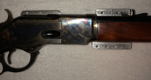
Figure 7: Placing rifle inside of left mount bracket
Attaching the Range Raider bracket onto the rifle is fairly straight forward. As shown by Figure 7, the left bracket is laid flat and the rifle is placed inside of it.
Click Enlarge
Figure 8: Right mount bracket placement and bolting
Once in place then the right bracket is lined up with the left bracket and placed over the rifle and bolted in place; see Figure 8.
Click Enlarge
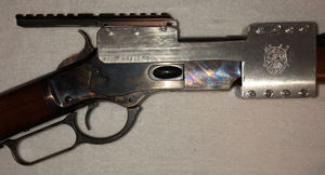
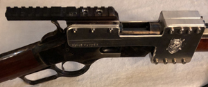
Figure 9: Offset overhead view of the Range Raider attached to the rifle
When the mount bracket is bolted around the rifle, Figure 9 illustrates an offset overhead view. At this point equipment can be attached to the picatinny rail, such as an optical scope! However, unless you prefer to attach shiny, reflective metal to your rifle, scoring and then painting the surface of the Range Raider mount bracket is in order (scoring the surface with a medium grit sandpaper will help paint stick to the metal surface and reduce broad off-flaking or peeling).
Click Enlarge
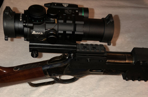
Figure 10: Painted Range Raider with attached scope and tactical flashlight/laser
Once painted, an optical scope can be mounted to the rifle as shown in Figure 10 (the scope shown is a Burris Armalite 3x32mm rifle tactical prism sight with an anti-reflection tube [link]). One thing that you may also notice is that a flashlight/laser is also attached (the flashlight/laser shown is a tactical 20mm picatinny rail green laser pistol light [link]). While it is widely understood that an optical scope is used for extended range, the use of a flashlight/laser may not be too well known for use with a rifle. In fact, the attachment of a flashlight/laser may be uncommon even with modern rifles with picatinny rails. The reason I opted to also add a flashlight/laser is to allow the lever-action rifle to be used more accurately at shorter ranges without using the optical scope where fast, on target sighting is needed.


Range Raider Personalization
Click Enlarge
Figure 11: Etched Personalization
The Dremel etched illustration that you may have noticed on the Range Raider is not part of the Range Raider design, so it is not present in the CAD files. The illustration (see Figure 11) was added manually by myself who happens to be a fan of "The Book of Boba Fett" series released on Disney+ featuring Tusken Raiders (referred to as Sand People in the original motion pictures).

Since the Range Raider is an after-market addition to a centuries' old rifle design, with the purpose of increasing the effectiveness of the rifle, it seemed fitting to etch a Tusken Raider onto the brackets considering Tuskens are thought to be low-tech and make moderate improvements to items. To wit, the centuries' old Winchester rifle in this example being low-tech and improved upon with the addition of a modern scope and tactical laser attachment...it is something you may find a Tusken wielding with great prowess.


Range Raider with Tusken
Range Raider with Rifle and Tusken Raider


Note: I found the 1:7 Tusken Raider statue here.

Desire to achieve balance is rarely tuned to the domain it is realized within, thereby recasting it into atypical substance.

About Joe
Find Out Now!