OSM-20 Experimental Face Mask

Parts that were used for this particular OSM-20 Prototype included:
|
|

|
During this step I dis-assembled the items containing the miniaturized lamps, keeping the lamp wired to the small control circuit. Once extracted, two jumpers needed to be soldered to bypass specific components on the board (their location may vary so some knowledge of electronics may be needed to identify and test them). The two jumped components were the power switch and a motion switch. |

|
There are two breather frames that are part of the OSM-20. Over the next few steps I show how to assemble the lamps and airflow guide that will go into each breather.
In this step set one of the lamps face down (so you do not see the lamp) on the table, then the airflow guide and then another lamp (face up so you see the lamp). |

|
Glue the airflow guide onto the lamp that is facing up. |

|
Glue the lamp (that if facing down) onto the airflow guide. This creates a air cavity where the lamps are facing each other with a gap between them. |

|
Place the assembly into the breather. There are some "dowels" that are part of the OSM-20. These "dowels" will need to be trimmed somewhat and then glued to the inside of the breather so that the small circuit board is separated from the lamp assembly and prevent the small circuit board from moving freely around. |

|
Glue and insert the positive and negative terminals into the 6 volt battery case so the positives are on one side and negatives are on the opposite side (so the batteries will be in parallel). Then wire and solder the positives together and separately the negatives. |

|
Clip out the three filter cap meshes using the silver mesh. After they have been trimmed you should be able to insert the mesh into the end of each filter frame and glue them in place. |

|
Clip out filters for each filter from the activated charcoal filter. Several were clipped out for each filter frame and then inserted into those frames. |

|
Glue the nose plate to the mask frame as well as the cheek plates. |

|
For each breather, set it next to each side of the mask. Align the back end of the breather next to the mask approximately where the red line is located. Then, toward the front end of the breather align the U bar so that it aligns with the front edge of the mask (see red line for reference) and glue it in place. Be sure to use enough glue as to form a seal on both sides of the assembly in the breather so that, when the breather is glued to the side of the mask, air from inside the breather will have to go through the assembly (where the lamps are) to get to the front end of the mask. |

|
Glue each breather to the mask. |

|
Glue each breather plate to the end of each breather. |

|
Glue the front shroud to the front of the mask; it should slip around the protruding breathers. |

|
Wire up the battery case, switch, and wiring from the assembly (that was placed in the breathers). Then position and glue the battery case to the mask as well as the switch container. |

|
Add foam strip to the inner portion of the mask (as to form a air tight seal between the face and the mask). Insert the large rectangular filter into the hole in the front of the mask; you will need to create a custom seal around the edge of the rectangular hole so that it is air tight; unfortunately I had no printer capability to print a flexible gasket seal. |

|
Slide on the smaller rectangular filter onto the end of the left breather. |

|
Slide on the smaller rectangular filter onto the end of the right breather. |

|
Assembled front view of the OSM-20. |

|
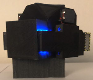
Assembled side view of the OSM-20 with the assembly inside of the left breather running. Note: the light grey colored cubed foam block visible below the mask is not part of the mask.
A fully assembled OSM-20 face mask has the approximate dimensions (inches as L x W x H): 8.5 x 7 x 4.75. Fairly compact and lite with all plastic construction. |